


What Needs to Be Measured Before Installing Glass Balustrades?
July 10, 2026
Successful glass balustrade installations begin with precise planning and accurate measurements before any glass is fabricated or hardware is installed. For property owners considering glass balustrades in Sydney, understanding the dimensions that affect panel sizing, barrier height, fixing locations and site access can help minimise installation problems, support compliance and achieve a clean, durable result. Poolsafe Fencing carefully assesses each site so the completed system can be designed around the actual structure and finished conditions.
This article explains the essential measurements required before installing glass balustrades on balconies, decks, patios and stairways, as well as glass barriers that form part of a pool enclosure. It covers layouts, finished floor levels, fall heights, fixing points, panel dimensions, clearances, obstacles and installation access.
Where a glass barrier is located near a swimming pool or also forms part of a pool enclosure, both fall-protection and pool-barrier requirements may need to be considered. Identifying this early is important because the applicable heights, gaps, clearances and non-climbable areas may differ depending on how the barrier will be used.
The existing layout of a balcony, deck or stairway determines where the balustrade can be positioned, how the glass panels will be arranged and which fixing system is suitable.
Before panels are ordered, the entire footprint should be measured so the proposed glass line can be compared with the structure below it. This assessment may reveal uneven surfaces, out-of-square corners, changes in level or areas where suitable structural fixing points are not available.
Identifying these conditions early allows the installer to adjust panel sizes, fixing positions or hardware rather than attempting to make prefabricated glass fit an unsuitable space.
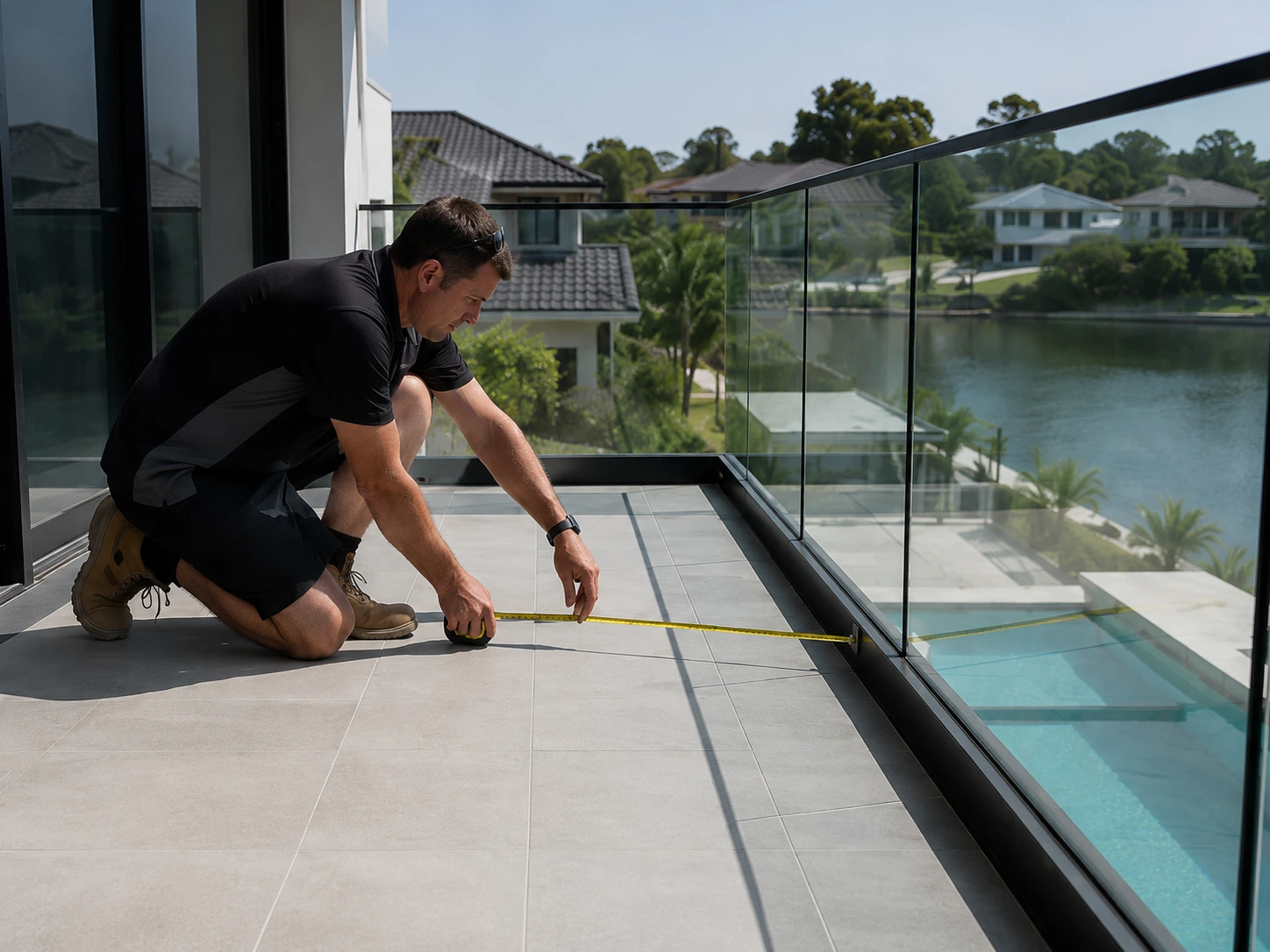
The first step is to establish the exact line the balustrade will follow. Measure each straight run from end to end, including returns around corners and any changes in direction.
Internal and external corner angles should be recorded rather than assumed to be 90 degrees. Existing decks, balconies and walls are often slightly out of square, and even a small variation can affect corner panels, handrail joins and hardware alignment.
Where the balustrade will be set back from the outer edge, measure the distance between the finished edge and the proposed fixing line at several points. The glass may need to sit further back to accommodate structural requirements, waterproofing details, edge clearances or the selected fixing system.
For stairways, record:
These measurements allow raked or stepped glass panels to follow the stair profile accurately.
A laser level, spirit level or other suitable measuring equipment should be used to check the complete balustrade run.
Record any high or low points that could affect:
Uneven surfaces may require packing, shimming, local surface preparation or another approved adjustment before the glass is installed.
Walls and structural edges should also be checked for plumb and straightness. A wall that bows or leans can affect the fit of an end panel, wall-mounted channel or handrail bracket.
Finished floor levels and fall heights must be confirmed before the glass height is finalised. These measurements influence the required barrier height and help determine whether the proposed system will continue to comply once tiles, decking or other finishes are installed.
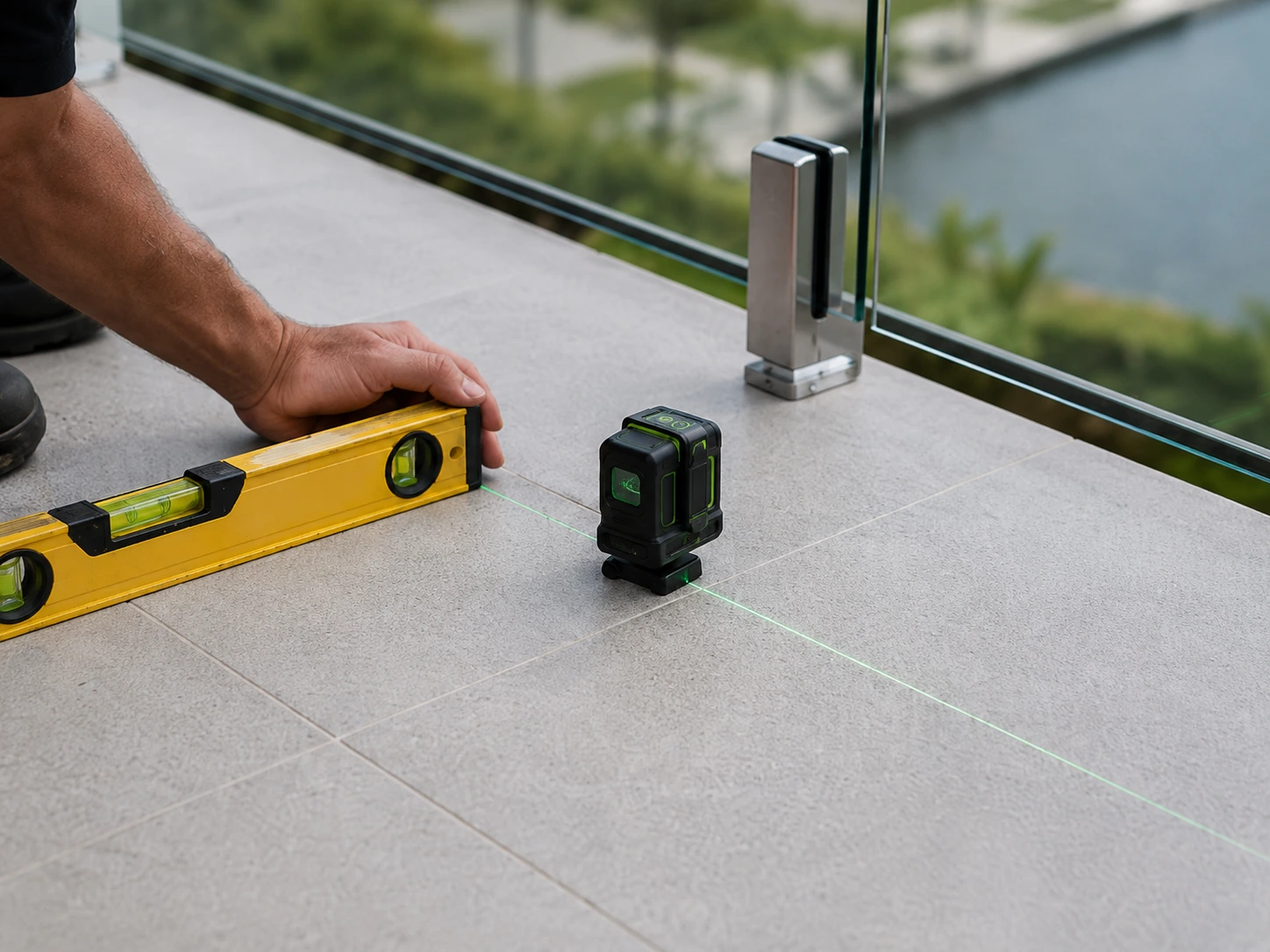
Finished floor level refers to the completed surface people will stand on, rather than the structural slab, unfinished deck frame or substrate underneath.
Measurements should account for all proposed surface build-ups, including:
Even a relatively small change in the expected finished floor level can reduce the effective barrier height and potentially create a compliance issue.
Where adjoining surfaces sit at different levels, record the location and height of each transition. This may occur where a balcony meets an internal floor, a tiled area meets decking or a landing connects with a stair flight.
Using a consistent reference point, such as a laser datum, helps ensure builders, tilers, glaziers and other trades are working from the same levels.
Fall height is the vertical distance between the relevant walking surface and the surface below. It helps determine whether a barrier is required and which design provisions apply.
Measurements should be based on the proposed finished levels on both sides of the balustrade. Landscaping, paving, planter boxes, retaining walls or future fill can alter the effective height of the fall and should not be ignored.
Fall height should be established using the measurement method applicable to the particular building design and barrier location. Unusual level changes or complex layouts may need to be reviewed by the project designer, engineer or certifier before glass heights and fixing details are finalised.
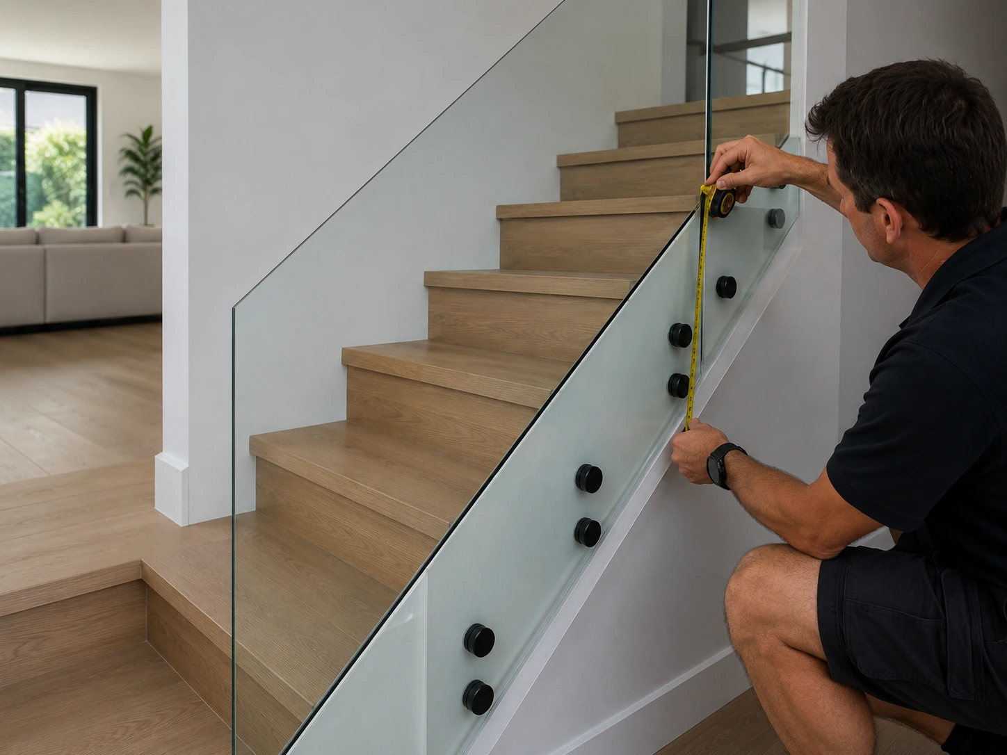
Stair balustrades require more than one height measurement. The rise and going of each step should be recorded, together with the location of tread nosings, landings and the transition between level and raking sections.
Measurements are generally taken in relation to the relevant tread or landing surface and the proposed top of the glass or handrail line.
This helps confirm that the completed barrier will maintain the required height:
Variations in riser height or tread depth can create uneven gaps below the glass or an inconsistent handrail line. Measuring every step is more reliable than assuming the staircase has been constructed uniformly.
The position of edges, raised surfaces and possible footholds can affect both balustrade design and pool-barrier compliance.
Measure the horizontal and vertical relationship between the proposed glass line and nearby features such as:
Record:
For barriers that form part of a pool enclosure, nearby climbable features may affect the required non-climbable area or barrier position. A narrow ledge, step or raised surface can effectively reduce the working height of a pool barrier if it is close enough to be used as a foothold.
Where a glass balustrade also functions as a pool barrier, the design should be checked against both sets of requirements before fabrication.
Glass balustrades must be fixed into a structure capable of supporting the loads transferred through the glass and hardware. Surface measurements alone are not enough; the material and structure beneath the finished surface must also be assessed.
For concrete balconies, patios and stair landings, record:
Fixings should not be positioned too close to slab edges or over weak screeds, unsupported topping slabs or hollow areas.
The required anchor type, diameter, embedment depth and edge clearance will depend on the hardware system, engineering requirements, concrete condition and manufacturer instructions.
Where waterproofing is present, the fixing method must also allow penetrations to be sealed correctly.
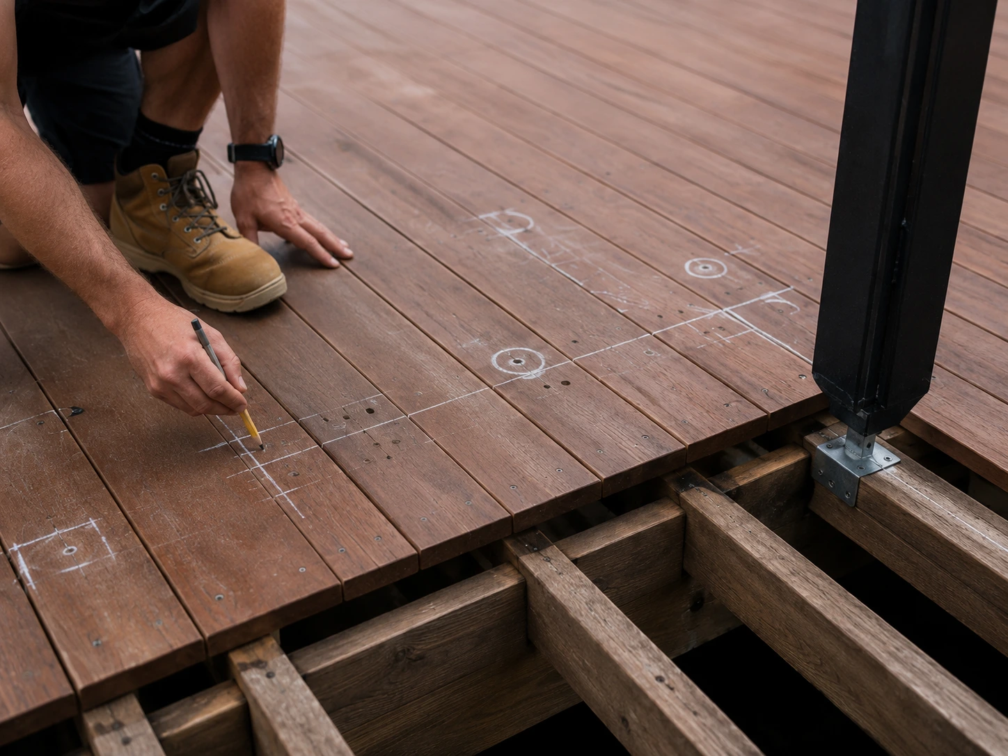
On timber decks, identify the location, depth and spacing of joists, bearers and other structural framing.
Spigots, posts and brackets should be fixed into suitable structural members rather than decking boards alone. Decorative boards may conceal the actual framing layout, so measurements may need to be confirmed from underneath the deck, from construction plans or through controlled inspection.
Record:
If the framing does not align with the preferred glass-panel layout, additional structural work may be necessary before installation.
Where the balustrade will connect to structural steel, identify the position, size and orientation of each member.
The glass layout and hardware should be coordinated so fixing points do not conflict with welds, flange edges, service penetrations or inaccessible areas.
Any drilling, welding or modification of structural steel should be assessed as part of the design rather than decided during installation.
Measure from the finished edge of the slab, deck or stair to the centreline of each proposed fixing.
Adequate edge clearance helps reduce the risk of:
These measurements help determine whether the preferred system can be installed or whether the glass line, post position or fixing method needs to change.
Panel sizing should be finalised only after all clear dimensions, fixing positions, corners and site obstructions have been recorded.
Toughened safety glass cannot be cut, drilled or resized after the toughening process. Panel dimensions, holes, notches and hardware locations must therefore be confirmed before fabrication.
Each measured run is divided into individual glass panels based on:
Where practical, panels can be arranged in consistent widths, with slightly adjusted end panels used to accommodate irregular overall dimensions.
Panels that are unnecessarily wide may be difficult to transport and install and may require more substantial hardware. Very narrow panels can create a cluttered appearance and increase the number of fittings required.
Final panel sizes must remain within the limitations of the selected glass, hardware and engineered system.
Panel joins and hardware positions should align with suitable structural support wherever possible.
Measure and mark:
This information helps prevent a spigot, post or channel fixing from being positioned over an unsupported edge, joint, void or inaccessible area.
On stairs, the relationship between tread depth, riser height and the glass setback affects where panel edges can be positioned and how the raking panels meet the landing panels.
The intended gaps between panels, walls, posts, floors and other components should be included in the layout rather than added after the panel sizes have been selected.
Check clearances at:
The allowable dimensions depend on the application and selected system. Pool barriers, balustrades and stair barriers may be subject to different gap and clearance requirements.
Each hardware component must be measured in relation to the structure, finished floor and adjoining glass panels.
For post-supported balustrades, establish the centre-to-centre spacing before the glass is ordered.
Post spacing must suit the engineered system and glass panel dimensions. The layout should also allow adequate edge clearance for the fixings and maintain a balanced appearance across each run.
Measure from the finished floor level to the intended top of each post, particularly where a handrail or top rail must achieve a required barrier height.
Spigot and channel positions should be marked along the proposed balustrade line and checked against the structure below.
Record:
A continuous base channel may require a straighter and more level fixing surface than individual spigots. Surface irregularities should therefore be identified before the system is selected.
Handrail runs should be measured from end to end, including corners, wall returns and changes between level and raking sections.
Record:
These measurements help reduce unnecessary joins and ensure brackets align with posts or other suitable fixing points.
Nearby walls and fixed objects can influence panel sizes, hardware placement and installation access.
Where a glass panel terminates at a wall, measure from fixed reference points to the proposed balustrade line at several heights.
Check whether the wall is:
Record any skirting, trims, render, tiles or projecting finishes that could interfere with a channel, handrail bracket or end panel.
Corners should be checked with a reliable square or digital angle finder. A corner that is not exactly 90 degrees may require adjusted panel dimensions or specialised hardware.
Measure clearances around sliding doors, bifold doors, hinged doors and window openings.
The glass and hardware must not interfere with:
Where a door opens towards a balustrade, allow enough space for safe operation without the door or handle striking the glass.
Every fixed element within the balustrade zone should be located from at least two reliable reference points.
This may include:
Record the height, width and projection of each obstacle so the glass line or panel sizes can be adjusted where necessary.
Before drilling, available plans should be reviewed and concealed services located where required. Fixing positions should not be based on assumptions about where electrical cables, plumbing or drainage lines are located.
Where the glass barrier includes a pool gate, the opening must be measured separately from the surrounding fixed panels.
The gate layout should allow for:
The gate should be positioned where it can open and close without contacting steps, walls, garden features or other panels.
The surrounding panels and posts must also provide suitable fixing positions for the selected hinge and latch system. Incorrect measurements can result in a gate opening that is too wide, too narrow or unable to accommodate the required hardware.
Access is often overlooked during the design stage, but it can determine the maximum practical panel size and the equipment required for installation.
Measure the route from the delivery point to the balustrade location, including:
Allow additional clearance for protective wrapping, carrying equipment and safe handling.
Narrow hallways, low ceilings, tight stair turns and fixed cabinetry may prevent large panels from reaching the installation area. In these situations, more narrow panels may be more practical than fewer oversized panels.
External access should also be checked for steep gradients, loose ground, slippery surfaces and overhead obstacles.
For upper-level balconies, rooftop terraces and multi-storey stairwells, confirm how installers and glass panels will reach the work area.
Access may involve:
The capacity and reach of the available equipment may influence panel weight, thickness and width.
Where glass must be lifted over a parapet or passed through an upper-level opening, measure the available clearance before the panels are ordered.
Accurate site measurements allow the quotation to reflect the actual number of panels, hardware requirements and installation conditions.
A detailed measure helps identify:
Without this information, an initial quote may not account for the full scope of the project.
Accurate measurements also reduce the risk of:
Because toughened glass cannot be altered after fabrication, even a small measurement error may make a custom panel unusable.
Pool barriers and balustrades are also subject to dimensional requirements concerning heights, gaps, fixing systems and nearby features. Measuring finished levels, fall zones, steps and potential footholds before ordering materials helps identify compliance concerns while changes can still be made to the design.
Accurate measurement is the foundation of a successful glass balustrade installation. The process involves more than recording the total length of a balcony, deck or staircase. Finished floor levels, fall heights, structural support, corners, panel gaps, hardware positions, obstacles and site access must all be assessed together.
Careful planning before fabrication reduces the likelihood of costly rework and helps ensure each panel and fitting suits the actual site conditions. It also provides a clearer basis for quoting, engineering and compliance assessment.
By completing a thorough site measure before glass is ordered, Poolsafe Fencing can plan a balustrade or pool-barrier system that fits correctly, performs reliably and achieves a consistent finished appearance.

